Dovetail twistlock
Weldable dovetail twistlock for securing containers to structures or structures to containers; available in 45° and 55° configurations, left-hand (standard) and right-hand options.

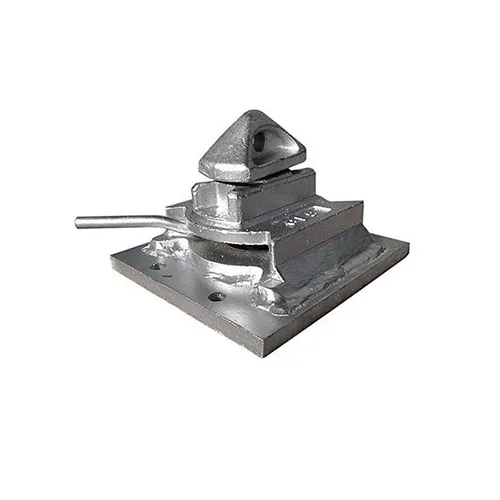
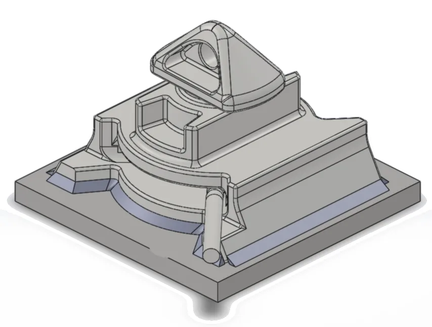
Dovetail twistlock welded to a 200 x 200 x 16 mm base plate — the standard fabricated boltable, and the starting point for any bolt pattern, footprint or mounting arrangement a site requires.
No prices online — quotations are prepared per application and quantity, usually within one business day; a more involved enquiry may take a little longer.
| Material | Dovetail twistlock casting (heat treatable steel) welded to a mild steel base plate |
|---|---|
| Load Rating (SWL) | As per the dovetail twistlock — SWL 250 kN tension / 210 kN shear (MBL 500 kN / 420 kN) |
| Dimensions | Base plate 200 x 200 x 16 mm as standard; other footprints and bolt patterns made to suit |
| Finish / Coating | Hot dip galvanised, or weldable primer where site welding follows |
| Standard | ISO 1161 (corner casting interface) |
Load ratings are as published in the TLA 2026 catalogue. Site-specific ratings and certification: on request.
Container buildings and site offices; MCC and switchgear containerisation; structural framing; any installation where the standard ABD-D1 footprint does not suit the foundation.
Where the standard bolted-on casting does not fit the foundation, the same dovetail twistlock is welded onto a base plate made to suit. The standard plate is 200 x 200 x 16 mm, hot dip galvanised, and is the version shown here. From that starting point the footprint, bolt pattern and plate arrangement are made to the job — single or double, fixed or slide-adjustable, and H-configuration sets for structural framing. Because the twistlock casting and the weld detail are identical regardless of the plate, the load rating is that of the dovetail twistlock throughout. Non-standard arrangements are quoted on application.
⬇ Download the datasheet (PDF · draft A)
◫ Request the 3D model (STEP) — WhatsApp engineering
◇ Technical drawing — included in the datasheet above.
Every one of these has been made and shipped. If your foundation matches one, say so on the enquiry and we work from a known pattern; if it does not, send the bolt centres and we draw a new plate to suit. Drawings are to scale and dimensioned in millimetres. The twistlock is shown in phantom for position — the outer outline is its plan envelope, 172 × 156 mm, and the inner one, 124 × 63.5 mm with R6.5 corners, is the part that passes through the corner casting.
Hot-rolled S355JR plate with the twistlock welded to it. The twistlock is the one cast part in the assembly.
Plate stands clear of the twistlock by 9.5 mm across and 40.5 mm along.
Same plate width as the 191 × 237, different bolt pitch — a bed drilled for one will not take the other.
Twistlock centres 178 mm; six holes, the centre pair shared.
The same construction, bolting down through slots rather than round holes — ±10 mm of adjustment per bolt.
S355JR, laser cut, blasted before welding, 8 mm fillet weld all round, hot dip galvanised after welding.
Same plate and same slots as the one before it — the twistlock is turned through 90°, and that is the whole difference.
One plate, two hands — left and right differ in the twistlock, not the hole pattern. Slotted holes with 7 mm end radii. A 25 × 45° chamfer on one side and a 15 mm radius on the other is what makes the plate handed.
The same twistlock spacing as the 368 × 237 double on a different plate. Slotted holes with 7 mm end radii. 25 × 45° chamfer on all four corners. Mild steel 16 mm.
Two twistlocks 160 mm from each end, both on the plate centreline. The plate gets longer; the fixing pattern does not get denser.
The same footprint whichever way it is built — only the penetration is drawn, because it is set by the corner casting.
The standard pitch is shown; hole pitch and diameter can be changed to suit, with additional cost and lead time. Available left and right handed.
The same 80 mm transverse pitch as the 200 × 200, 80 mm further apart along the plate — and Ø18 holes, not Ø14.
Cast, not fabricated — the footprint of the cast boltable twistlock itself.
Before you drill. These are footprints, not fabrication drawings. Before anything is drilled or cast in, ask us for the released drawing of the footprint you are working to — it carries the tolerances, the weld preparation and the material specification that a footprint cannot, and it is the document to build from.
Bolt sizes, grades and torque are not shown: they follow the foundation design, not the footprint. Load ratings appear on the product pages and on the individual drawings, not here — ask an engineer for a site-specific rating. Section 13 of the 2026 catalogue carries the same set.

Weldable dovetail twistlock for securing containers to structures or structures to containers; available in 45° and 55° configurations, left-hand (standard) and right-hand options.

Forged D-ring welded to a dovetail plate that slides into a dovetail slipper, giving a rated, removable lashing point wherever a slipper is already installed.

Weldable dovetail slipper (45° and 55°, single and double) providing a permanent socket for matching dovetail twistlocks, allowing containers to be repeatedly mounted and removed without a permanent twistlock.

ABD-D1 bolted-on dovetail twistlock — a single-casting chassis on a 16 mm base plate that bolts to a concrete foundation or steel structure, securing a container with no permanent modification to the container itself.